Expansion Joints
Creep compounded by column shortening can cause problems for a number of trades which follow the structural contractors.
Relative vertical deflection due to creep and column shortening
Creep compounded by column shortening can cause problems for a number of trades which follow the structural contractors. Many contractors for instance are more concerned about the relative deflection of adjacent floors rather than their absolute height above datum.
Creep deflections can be predicted with a fair degree of accuracy however column shortening is less easily dealt with. Like creep, column shortening varies with time, not only due to creep but also because the load increases gradually as extra floors are built, fitted out and handed over. Once again uniformity in plan is important as column size at each location and level should be matched fairly closely to the actual permanent load whereby the long-term shortening of each column should be broadly similar.

Lateral deflections
Lateral deflections are caused by the drying shrinkage of building components, thermal expansion and contraction due to temperature cycling and sway caused by wind loading. Movement due to shrinkage and temperature should be broadly similar at all levels within the structure, but lateral movement due to wind loading increases with height above ground.
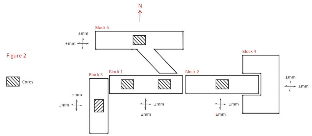
Cores within independently constructed units form effective anchors for determining and limiting lateral movement. This is illustrated in Figure 2 where the cores of each multi-storey block are centrally located and form an effective anchor for determining shrinkage and temperature movements. Block 1 is very stiff owing to the presence of two main cores and this restraint reduces the relative movement between it and the link-bridge. Block 4 as a single storey structure does not require a core.
The total horizontal movement at any point is determined by summing the long-term shrinkage, the temperature variation and the wind movement at each level of each block interface.
Where are expansion joint located?
One of the key elements in successfully locating expansion joints is plan uniformity. As Eurocode 8: EN 1998-1-2004 ‘Design of structures for earthquake resistance’ states: ‘Uniformity in plan is characterised by an even distribution of the structural elements which allows short and direct transmission of the inertia forces created in the distributed masses of the building. If necessary, uniformity may be realised by subdividing the entire building by [seismic] joints into dynamically independent units.’
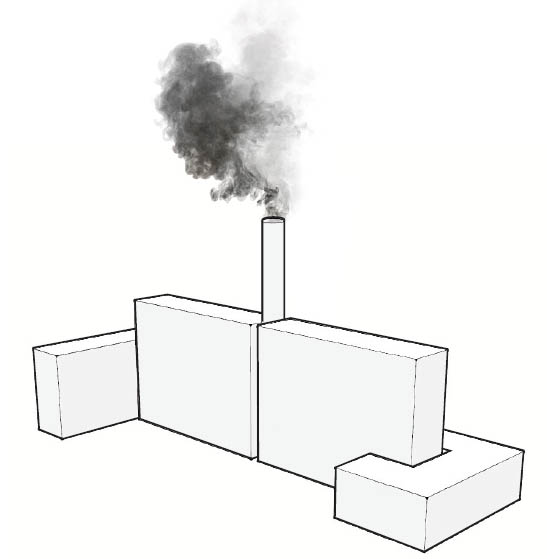
Figure 3 mirrors Figure 2 and shows the layout of a series of such dynamically independent units separated by expansion joints.
Expansion joint 1 subdivides the main building into two independent units. Such joints typically arise at 30 to 50 metre centres.
Expansion joint 2 lies between the main building and an adjoining multi-storey annex. This joint lies at a point where there is a change in direction between the two elements. An expansion joint may be required due to a number of factors including differential wind loading and the possibility that the structures were built at different times.
Expansion joint 3 divides the main high-rise structure from a lower height building and again differential wind loading and the possibility that the structures were built at different times may be factors in determining the location of this expansion joint.
Expansion joint 4 arises between a link-bridge joining the main building to an outlying structure. This expansion joint allows the link-bridge to accommodate movement from temperature variation and wind loading which will cause it to oscillate to and fro about a mean position.

Installing fire barriers beneath expansion joints
 It may seem strange to install fire barriers beneath expansion joints until one considers that in the event of fire they act as chimneys funnelling toxic smoke and flames through the building and often through fire compartment walls.
Using mineral wool as a fire barrier in expansion gaps
In some instances a designer may specify mineral wool as the fire barrier in an expansion gap. However mineral wool will compress when the expansion gap closes but will not expand when it opens. As a result toxic smoke and flame bypass the mineral wool infill and pass through compartment walls.
It is prudent to install fire barriers with a matching rated movement capacity beneath expansion joints that pass through compartment walls.


