Control Joints (part 2)
Finishes will often crack because no consideration has been given to the structure underlying the finishes zone.
Putting control joints in their place
The problem with following the simple dogma of randomly forming 6 metre or 3 metre bays to suit paving aesthetics is such that finishes will often crack because no consideration has been given to the structure underlying the finishes zone. There are very few cases in which the tiling contractor is responsible for cracking that occurs in finishes and yet invariably they are blamed.
Bay size and the movement capacity of the control joint system are not the only considerations which must be borne in mind when determining control joint spacing and locations. This is particularly important when flooring is installed on suspended, beam supported slabs. The exigencies of modern construction means that almost all large scale structures are build using suspended construction techniques and even slabs which seem to be ground supported are actually laid on ground beams.
Worldwide hard flooring standards are suitably vague when it comes to giving advice on joint location and the tiling contractor is often advised to seek the advice of the designer or engineer. For instance, BS 5385 states that: ‘At the design stage the magnitude of any stresses should be assessed and a decision should be made as to where movement joints, flexible joints and contracti on joints are to be located, having regard to all the relevant factors including the type of flooring and bed’.
Nevertheless some direction is given within BS 5385 Part 5 and this may be summarised as follows: ‘Flexible joints should be used at floor perimeters and to divide the flooring into bays at the intervals give in the relevant flooring sections. Where possible they should coincide with structural features such as columns or door openings….’
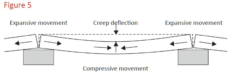
 ‘Flexible joints should be inserted over supporting walls and beams and at intermediate positions to accommodate deflection of the base and movements in the flooring.’ Creep is the reason control joints are inserted directly over beams and at ‘intermediate positions’. Over time beams (and slabs supported by beams) begin to sag from a combination of dead load (their own weight), super dead load (the mass of finishes etc.) and imposed loading which can be fixed or transient in nature.
Figure 5 above shows how beams creep over time. Creep happens progressively over the life of the structure, happening quickly at the beginning while components are still plastic with the rate of deflection slowing after the first few years. The implications for hard finishes fixed on top of suspended slabs can be significant if the control joints are placed in the wrong position… and particularly if the compressive forces generated at the mid-point of spans are not accommodated. BS 5385 is clear about the fact that control joints should be installed directly over beams but one has to look at BS 8110 ‘Structural Use of Concrete’ to find further advice about whether control joints need to be installed at the mid-point of the span of a concrete slab.

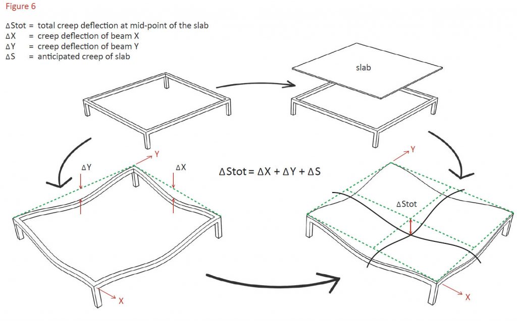
S 8110 advises that where the anticipated deflection at the mid-point of a span of concrete exceeds 20mm then hard finishes are likely to be compromised. As Figure 6 shows, suspended slabs supported by beams reflect the creep deflection exhibited by those beams. It can also be seen that the deflection at the mid-point of a slab is the sum of the deflection of the individual beams plus the creep deflection of the slab itself.
Hence the Project Engineer should calculate the anticipated magnitude of deflection for each beam (X and Y) at the mid-point of its span. These two values should then be added to the anticipated creep deflection of the slab to establish the anticipated deflection at the mid-point of the suspended slab. Where the combined deflections exceed 30mm further intermediate control joints dividing the zone into quadrants should be considered.
Control joint summary
The following should therefore be considered when determining the spacing and locations of control joints:
1. Control joints should have metal edge profiles if they are to be used in high traffic areas.
2. Control joints in internal floors should be installed between hard paving to form maximum 6 metres x 6 metres bays.
3. Control joints in external floors should be installed between hard paving to form maximum 3 metre x
3 metre bays. These control joints should have a wider flexible core than those used in internal locations.
4. When hard paving is laid on suspended slabs:
a. Control joints should be aligned with and be installed directly over all beams and supporting walls.
b. Control joints should be installed at the mid-point of slab spans where the Engineer advises that the anti cipated deflection at this mid-point is greater than 20mm. If the creep deflection exceeds 30mm then further sub-division of the paving may be necessary.
5. The impact of drying shrinkage and temperature variation upon the expansion and contraction of the flooring bays should be assessed and compared to the capacity of the control joint system to accommodate that deflection.
6. Control joints should be installed at perimeters and between paving and all up-stands which interrupt the floor surface.
7. Control joints should be inserted where there is a change of bedding or screed depth or flooring material depth or type varies.


